Kubernetes Networking From the First Principles

Table of Contents
We go from containers and network namespace to Pod-to-Pod, Pod-to-Service, and external-client-to-Service networking.
Pods
Containers of the same Pod share the same Linux network namespace, isolated from the host network namespace.
Each Pod gets a separate network namespace and is assigned a cluster-wide unique IP address from the cluster’s Pod CIDR range. Many managed Kubernetes offerings use Host-local IPAM (IP Address Management), so that each Node is fist assigned a subnet of Pod CIDR. Then, each Pod gets its IP address from the Node the Pod is on.
The Kubernetes networking model requires that a container in Pod A can reach a container in Pod B, crossing network namespaces, regardless of whether Pods A and B are on the same Node or not.
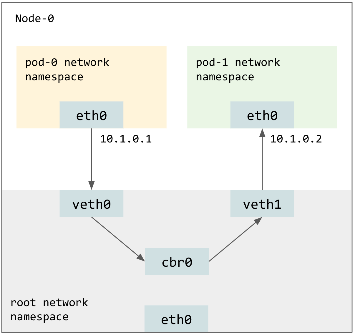
Pod to Pod on the same Node
For each Pod, kubelet will create a VETH (Virtual Ethernet Device) pair in the host network namespace. Packets transmitted on one device in the pair are immediately received on the other device. Then Kubelet will move one device of such pair into the Pod’s network namespace and rename this device to eth0 in the Pod’s namespace. Each VETH device remained in the host network namespace will be assigned a Pod IP and be connected to a software bridge cbr0.
Pod to Pod on another Node
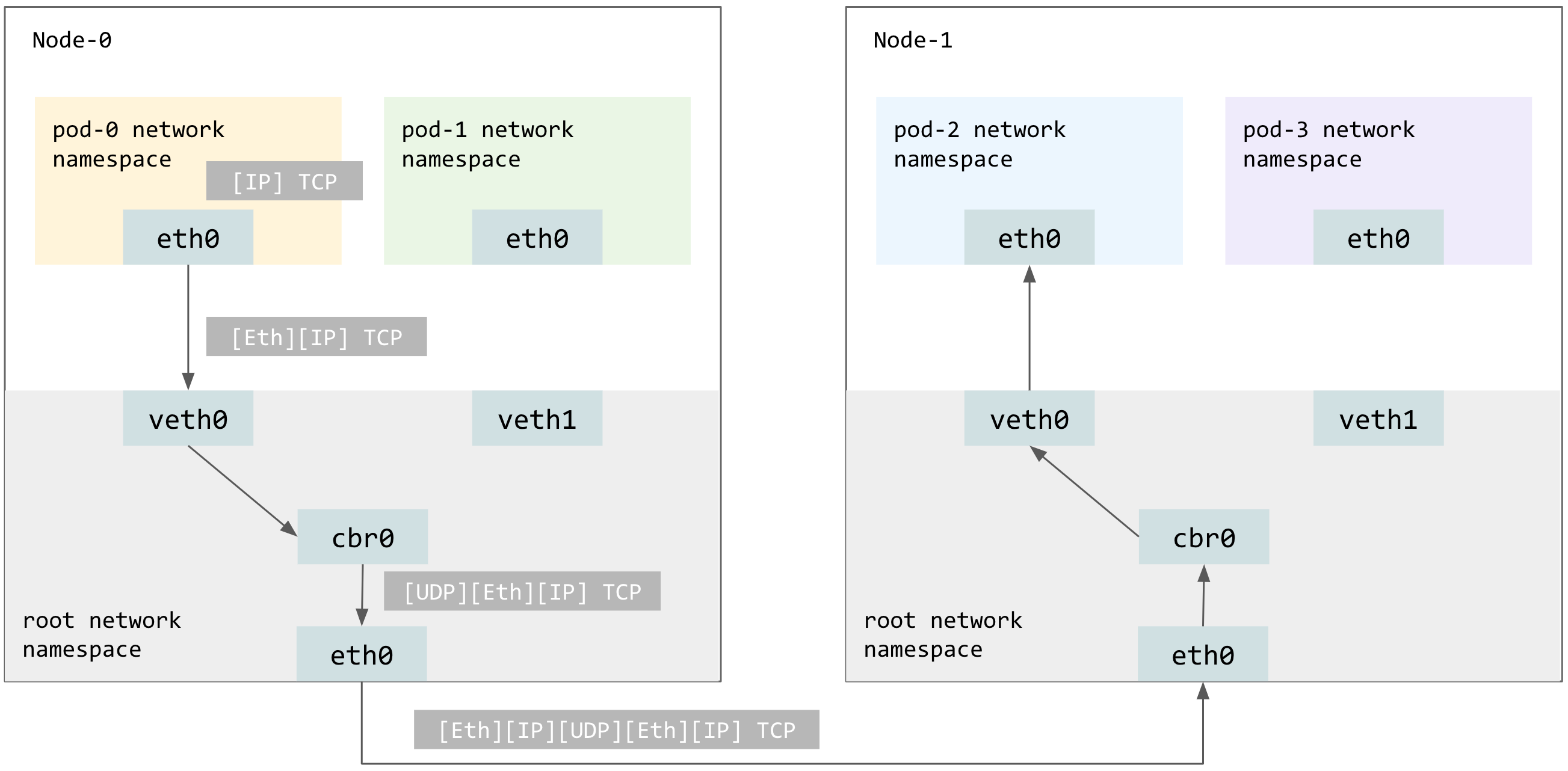
On Node-1, IP packets (whose source and destination addresses are the Pod IPs) sent by pod-1 will be encapsulated as Ethernet frames being sent to cbr0.
The cbr0 switch has a match-all forwarding rule for all packets destinated to anything but Node-1’s subnet of Pod CIDR. The CNI plugin in VXLAN mode will encapsulate the Ethernet frames as UDP packets. These UDP packets’ source and destination addresses are the Node IPs.
ClusterIP-type Services
Even though Pod IPs are routable, Pods (and hence the Pod IPs) are ephemeral by design. Hence, it is more reliable and recommended to use the Kubernetes Service, which provides a static cluster IP and load balancing over a group of Pods. The most basic Service type is ClusterIP, which represents a service available within the cluster but not exposed to the internet.
ClusterIP-type Services are implemented using kube-proxy, which is not a real proxy (data plane) but configures iptables to capture and NAT traffic to cluster IP of the Service.
Below is an example of pod-1 sending a request to service-1 backed by pod-0 and pod-2. Encapsulation details covered in the previous section are omitted from the diagram below.
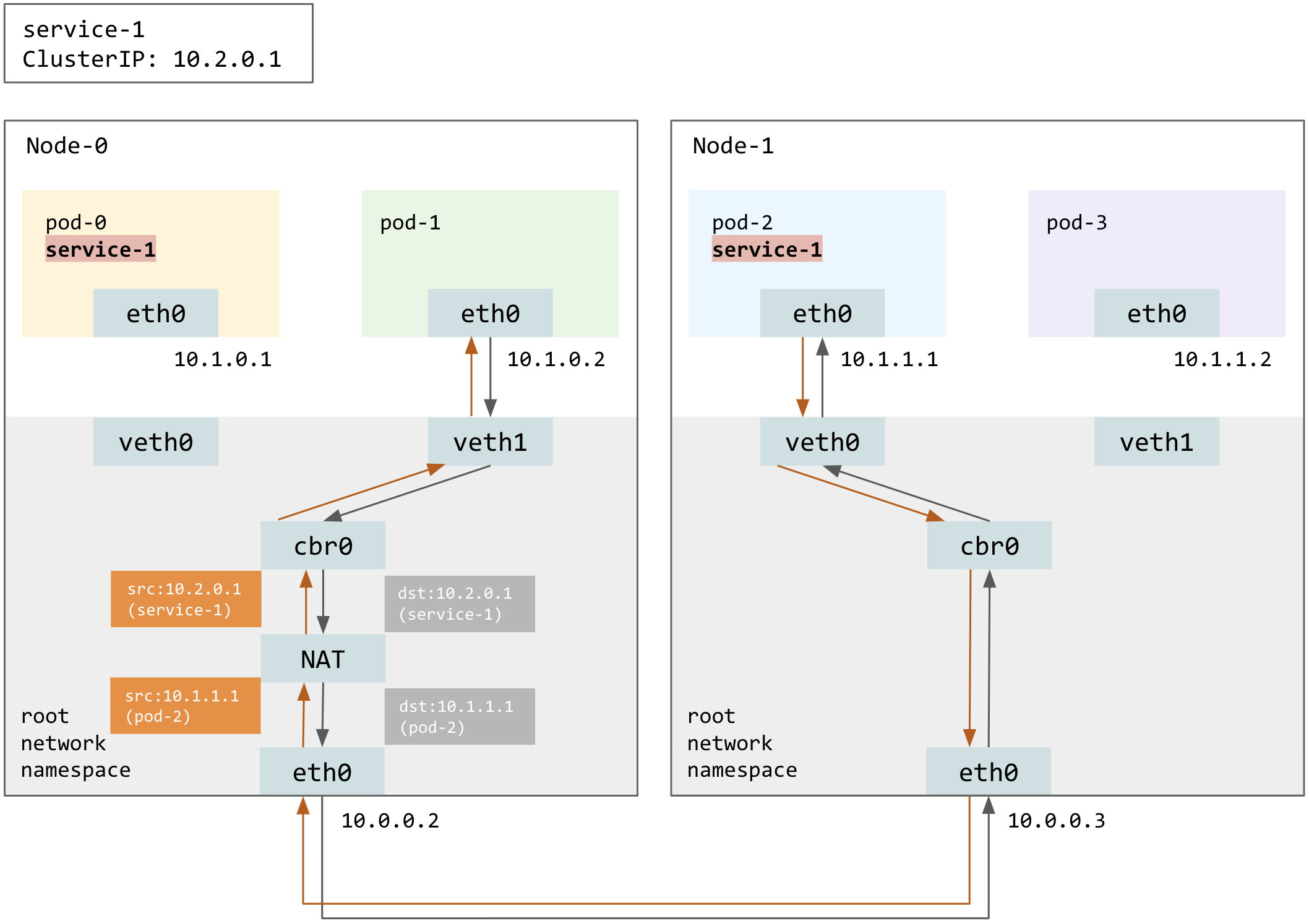
Kube-proxy will choose at random one of the backing Pods to serve the request, by dNATing the destination IP from the Service’s cluster IP to the IP of the chosen Pod, which in this example is pod-2. Note that the response from pod-2 will be sNATed back to the Service’s cluster IP, so that kube-proxy remains transparent to workloads. Otherwise, pod-1 only has connection states about service-1, not pod-2, and thus will reset the connection.
NodePort-type Services
To expose a service to clients outside of the cluster, use the NodePort-type Service, which reserves the same port on each Node such that the client could access the service by hitting the NodePort on any Nodes.
The example below assumes externalTrafficPolicy is set to Cluster, which means traffic can be routed to a backing Pod on a different Node. Here, the cluster-external client send requests to the NodePort of service-1 on Node-0, and kube-proxy chooses pod-2 to serve the request.
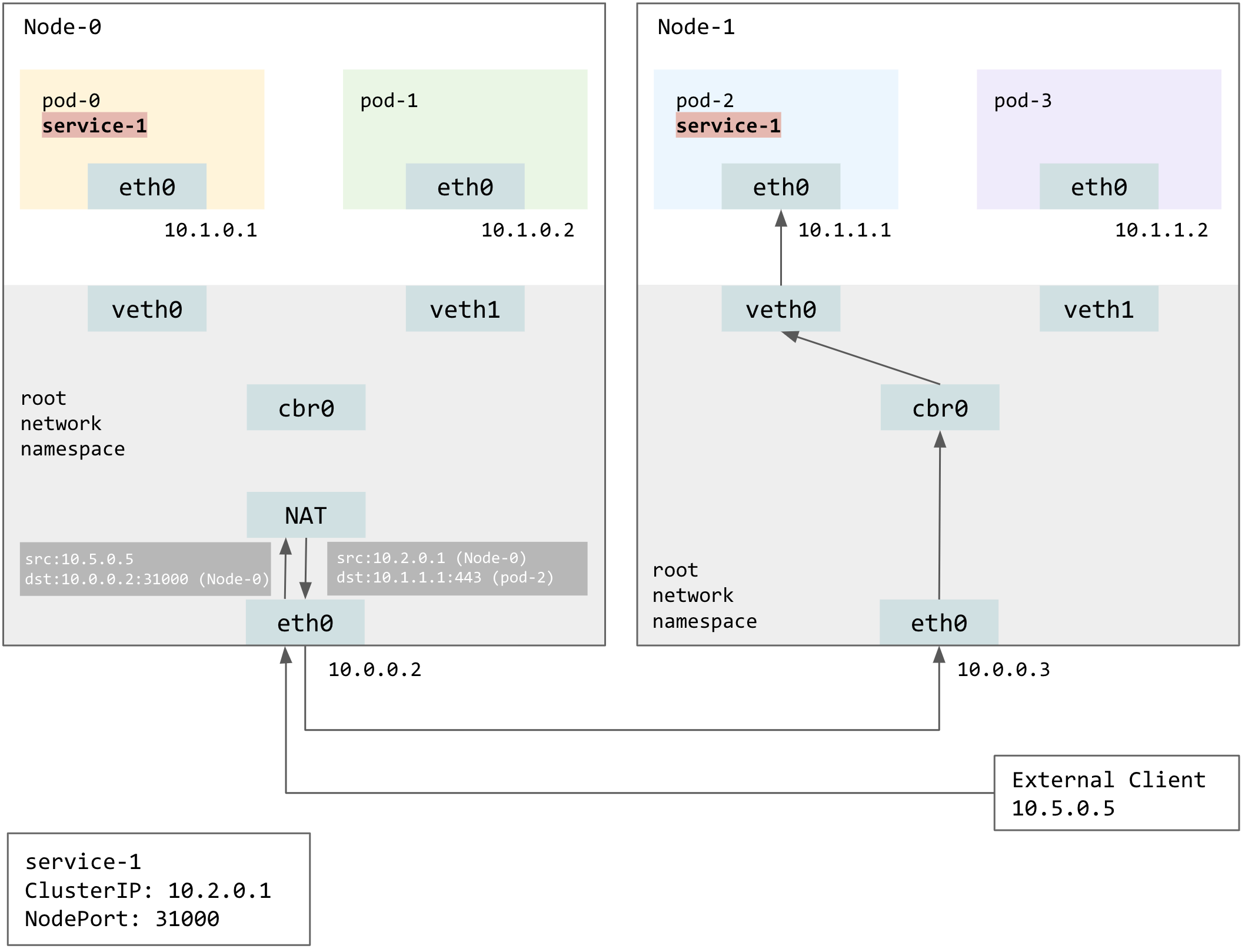
Obviously the destination address will be masqueraded from Node-0 to pod-2, but notice that source address is also masqueraded, from the client IP to Node-0’s IP. Source-NATing is necessary, because otherwise pod-2 will respond directly to the client, who assume it is maintaining a connection to Node-0.